How to Build a Simple Rain Sensor Circuit Using IC 555 - Science Fair Project
This is a simple science project which can be built by a school grade student very easily and can be used for displaying its relatively useful feature, probably among his friends or in a science fair exhibition. The circuit is basically rigged as a comparator and is typically configured to sense the low resistance through water across its relevant inputs.
Let’s try to understand how to build a simple rain sensor circuit using the IC 555:
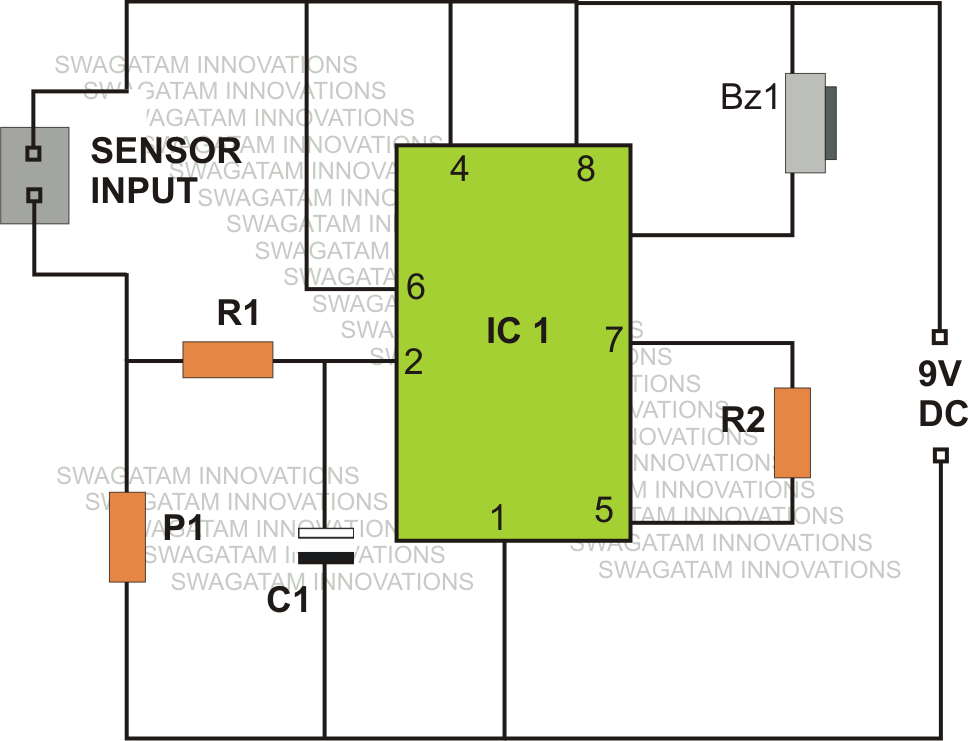
Referring the figure, we see a rather simple design made around a single active component which is the IC 555.
Other than the IC, the circuit just includes a few cheap passive components likeresistors and capacitors.
We are familiar the two important modes of operation of the IC 555, which are the astable and the monostable multivibrator mode, howver the IC is laid down in a rather unusual fashion, quite like a comparator.
As shown in the figure, sensing terminals are received across the positive and pin #2 of the IC via R1.
When water (due to rain fall) comes across the above inputs, a low resistance is developed here. The preset P1 is suitably adjusted such that any type of water across the sensing inputs triggers the IC appropriately.
The sudden low resistance at pin #2 of the IC acts like a pulse which exceeds the potential at pin #2 more than 1/3 of the supply voltage.
This activation instantly makes the output of the IC go low, ringing the connected buzzer. The buzzer circuit is comprehensively explained here, if you wanted to build one.
As long as the sensing input stays immersed under water, the output continues with the above situation.
However the moment, water is removed from the specified input terminals, the potential at pin #2 reverts to less than 1/3 of the supply voltage, making the output go high, back to its original position, switching off the buzzer.
The above operation effectively indicates the commencement of a rain fall when the sensor is appropriately placed for the detection.
The charge inside the capacitor C1 keeps the buzzer ringing for some period of time even after the water from the sensing inputs is completely removed.
Therefore the value of C1 must be appropriately chosen, or may be completely eliminated if the feature is not required.


Making the Sensor Unit.
The circuit obviously needs to be placed indoors, therefore only the sensor terminals are required to be positioned outdoors through long connecting flexible wires.
The figure shows a simple way of making the sensor unit.
A small plastic of around 2 by 2 inches is used and a couple metal screws are fixed over the plate. The distance between the screw should be such that no residual water is able to stick or clog between them and water formation across it is detected only as long as the rain fall persists.
The wires from the screws should be carefully terminated to the relevant points on the circuit. The circuit must be hosed inside a suitable plastic enclosure along with the buzzer and the battery.
Parts List
R1 = 1M,
R2 = 100K,
P1 = 1M preset, can be replaced with a 1M fixed resistor
IC = 555,
C1 = 10uF/25V, optional
Rain Sensor/Alarm Circuit Using the IC LM324

Parts List
R1 = 1M,
R2 = 100K,
P1 = 1M preset, can be replaced with a 1M fixed resistor
IC = 555,
C1 = 10uF/25V, optional
Rain Sensor/Alarm Circuit Using the IC LM324

No comments:
Post a Comment