How to Build an Electronic Spy Bug Circuit
Here we’ll discuss how to make an electronic spy bug circuit using two methods, one that consists of wire link from the transmitter to the receiver, and the other which is completely wireless and can be used to eavesdrop a particular conversation over a range of about 30 meters, over an ordinary FM radio.

Circuit Description of a an electronic Spy Bug Using Wire Link:
The proposed simple electronic spy bug circuit is basically a high gain amplifier using the IC 741 as the heart of the circuit and also a couple of high gain output transistors. The IC 741 if configured as a non inverting amplifier which performs the function of a pre-amplifier stage.
The gain of this IC 741 preamplifier stage may be varied as desired, using the pot across its input and output pin outs. The gain setting is used to set the sensitivity of the amplifier and is set to maximum so that even low volume speech conversation may be picked through it.
The mic at the input transforms sound vibrations into minute electrical pulses, which is further amplified by the IC 741 to suitable levels before applying it to the output amplifier stage consisting of a standard push-pull stage.
This push pull stage is made using a couple of high gain transistors 187/ 188.
Here, the signal received from the 741 output is suitably amplified so that it finally becomes audible over the speaker.

Parts List for the above opamp based spy bug circuit
R1 = 10K,
R2 = 10k,
R3, R4 = 27K,
R5 = 1.5 M,
C1 = 104,
C2 = 220uF/25V,
T1 = 188,
T2 = 187,
MIC = electret mic,
IC1 = 741,
Power = 9 volt battery
Headphone = 64 Ohms, or a small speaker of 8 Ohms, 2 inches
Wireless spy bug circuit description:
The purpose of this circuit is also the same as above, that is for catching weak sound signals or for hearing some hidden conversation, however the caught voice signals here is transmitted into the air instead of forwarding it through wire links.


The sent signals can be received over any standard FM radio, tuned accurately to the respective frequency.
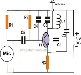
The above shown wireless spy bug circuit is basically a small RF transmitter built around a single transistor.
The circuit functions quite like a Colpitts oscillator incorporating a tank circuit for the generation of the required oscillations.
The frequency mainly depends on the positioning and the values of the inductor, C1, C2 and C3. The coil turn distance and diameter may be manipulated a little for optimizing best response over the FM receiver.
A small antenna in the form of a 3 inches wire may be attached at the shown point for making the “bug” highly responsive and generate distortion free signals.
For the 741 circuit, the speaker is only positioned and used as the receiver and may be placed in some other room, where the eavesdropping may be intended to be carried out.
The linking of the speaker from the amplifier circuit may be done through wire connections, preferably by using thin wires and escorting the entire length up to the speaker in some hidden way, probably by laying it under the carpet or across the corners of the room.
For the wireless spy bug circuit everything becomes pretty simple and you just have to hide the transmitter circuit in some suitable place, like under the table, couch, sofa etc.

Parts List for the above wireless spy bug circuit.
R1 = 3k3,
R2 = 100K,
R3 = 470 Ohms
R3 = 470 Ohms
C1 = 10 pF,
C2 = 27 pF
C3 = 27pF,
C4 = 102 disc
C5 = 10uF/10V,
Mic = condenser mic
T1 = BC547
L1 = 3 to 4 turns of 22SWG super enamel copper wire, 5 to 7 mm diameter, air core
Please refer the scanned image of the prototype for getting an idea regarding the coil dimensions.
C3 = 27pF,
C4 = 102 disc
C5 = 10uF/10V,
Mic = condenser mic
T1 = BC547
L1 = 3 to 4 turns of 22SWG super enamel copper wire, 5 to 7 mm diameter, air core
Please refer the scanned image of the prototype for getting an idea regarding the coil dimensions.
No comments:
Post a Comment